
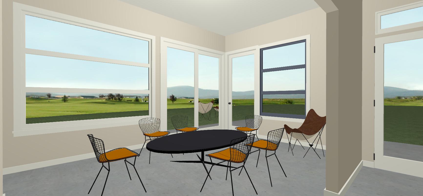
The schematic design phase of the Bay Vista project is over. Now is a good time to recap the design. As you may recall, the Bay Vista project, in Oakland, is a whole house remodel + an addition to a faintly Swiss cottage style California Ranch house that dates from the late 60’s. The owners want to take the house from it’s current 3 bedroom 2-1/2 bath size and enlarge it to a 4 bedroom 4-1/2 bath house complete with an office, a home gym, and a library. They want to maximize the indoor-outdoor connection between the main great room and the back terrace.
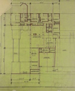
Image copyright 2015, David Locicero | architect
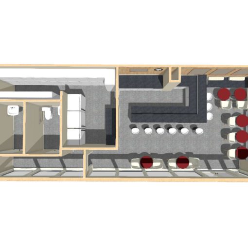
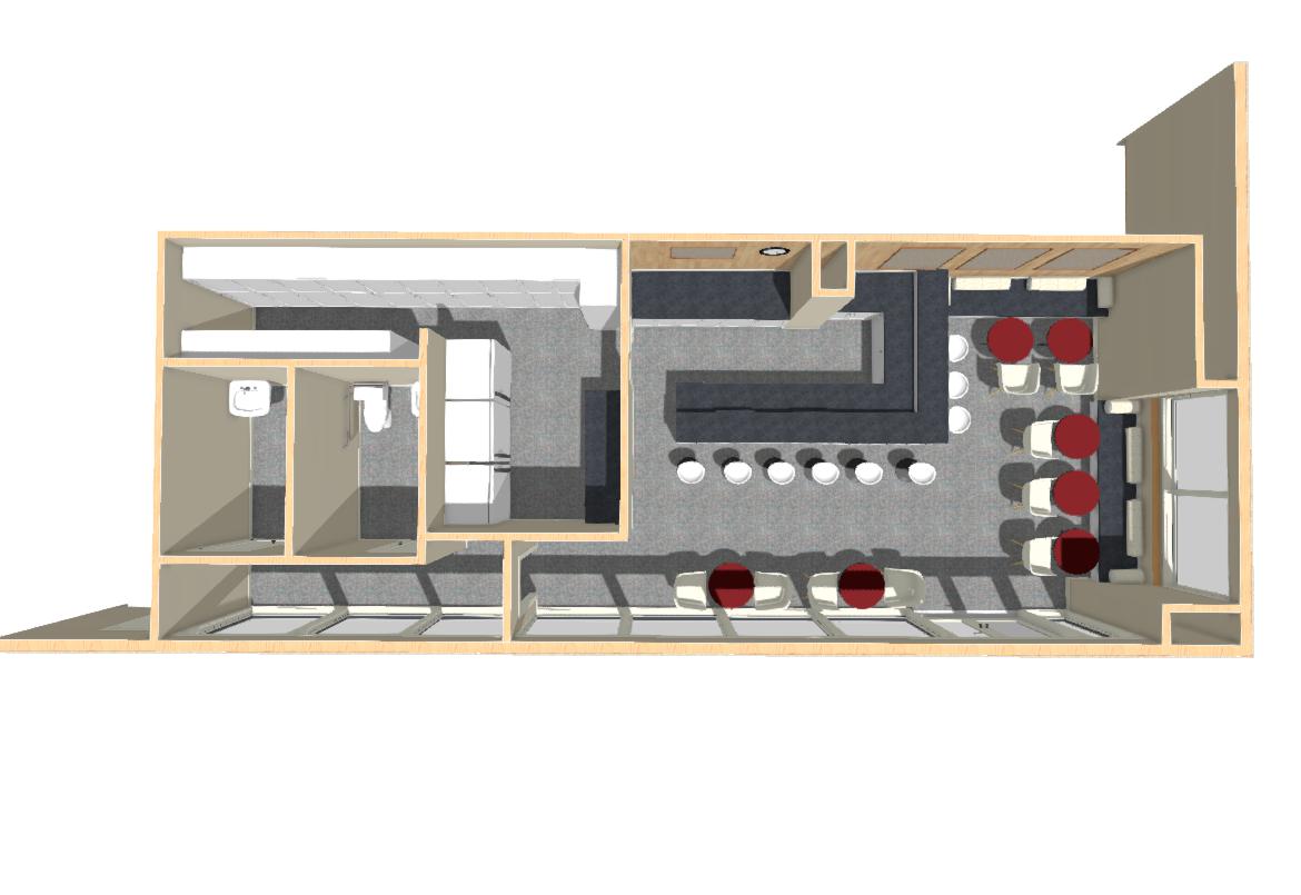
I originally developed 4 or 5 different ways to solve the space planning issues. The owners selected the plan above. Since that meeting we’ve met once. After some discussion about the elevations and what the clients wanted the house to look like, I went away and worked up some new drawings responding to their comments about the layout and some physical and bureaucratic limitations (confirming where the site starts to slope sharply and confirming set backs).
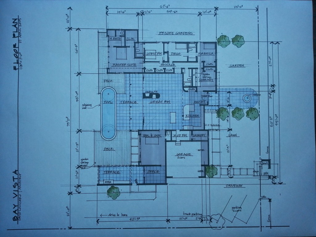
The new plan is both a bit simpler and more elaborated. The grey areas are the areas added to the existing house. I’ve also shaded the floor material that extends from the exterior terrace through the great room, entry and kitchen and out into the front yard. I did this for two reasons. First, it emphasizes the indoor-outdoor connection and how that entire area could be perceived as a single space. Second, it also makes clear that the new design is starting to have two solid blocks of rooms – at the top and at the bottom – with the “open space” between them as the great room.
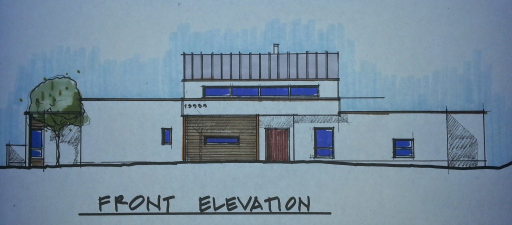
I am more satisfied with the way the front elevation looks now. I’ve extended the canopy that was at the front door, so that it extends the full width of the great room beyond. This helps to connect the left wing and the right wing of the house together and emphasizes the center of the house, and the entryway. There are still a few things that look unresolved to me. But we’ll be able to work on those things if and when the project moves into Design Development.
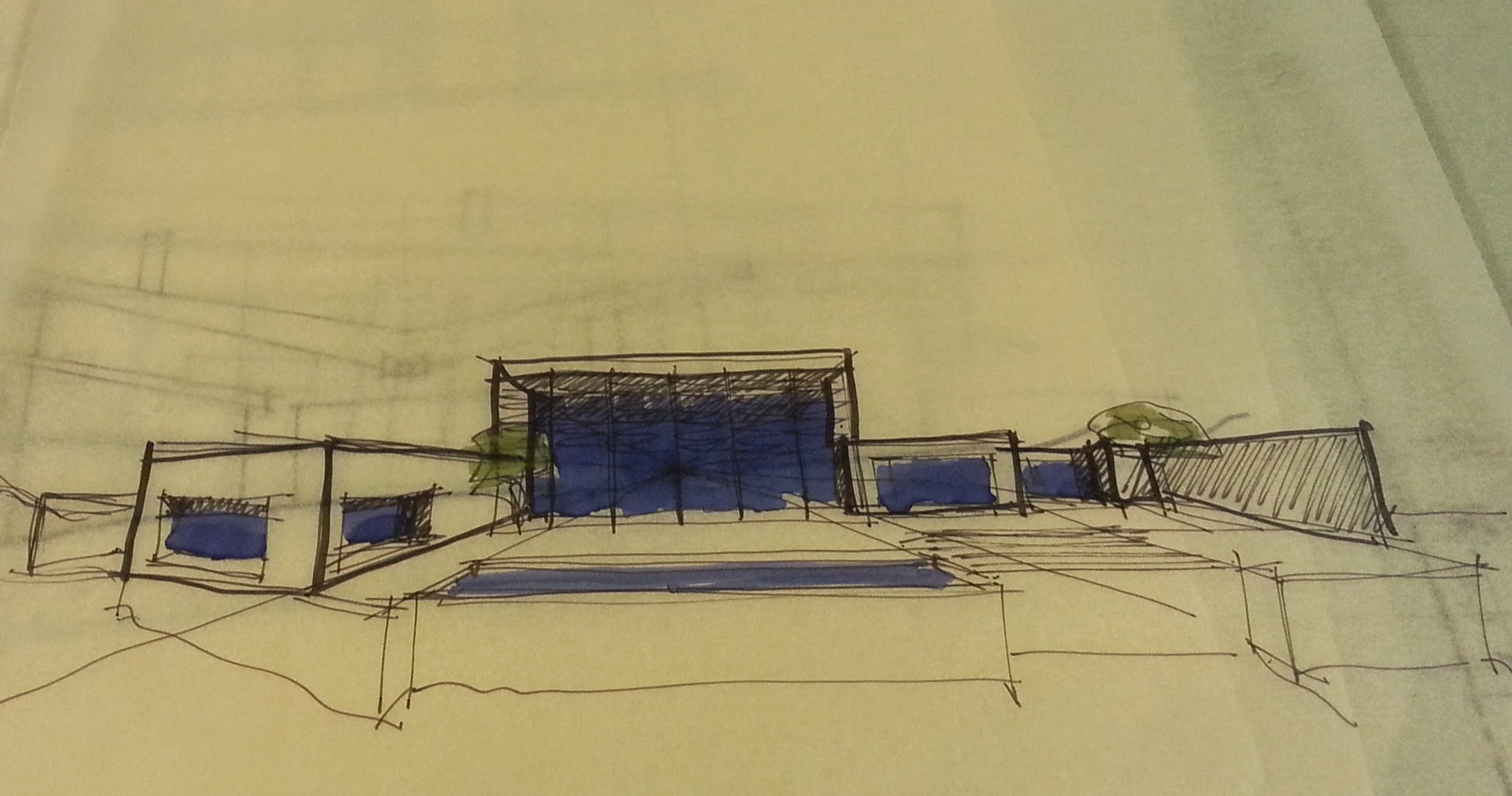
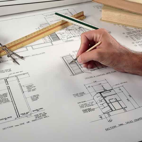
For those that are curious, yes, these drawings were done ink on tracing paper, then copied onto white paper and hand colored with design markers. I find that when attacking a project this complex, using analog tools early in the process helps me to fully understand all the parts and relationships in a way that is almost impossible if I were to have jumped into my computer design/CAD/BIM program.
CAD stands for Computer Aided Drawing
BIM is Building Information Modeling, an advanced form of computer drawing program that actually allows us to build a model of the building in the computer. It’s quite handy.
Analog tools require time and thought that computer tools deprive you of. Yes, speed is handy, but not at this stage of the game. If and when this project moves forward, I’ll jump into BIM with both feet.